Weight and Balance


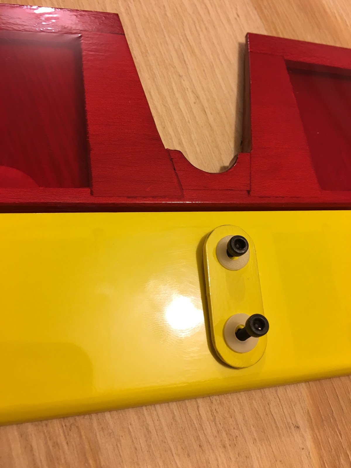
 The manual indicates that the CG should be at 115mm from the leading edge of the wing.
Like on the previous version of the Aether, even moving both the RX and Motor battery all the way forward I still had to add weight to the nose (21 g)
I secured the ballast externally using electrical tape so that I can move it easily. Once the CG is in the sweet spot I can mark the CG spot and re-balance the model internally.
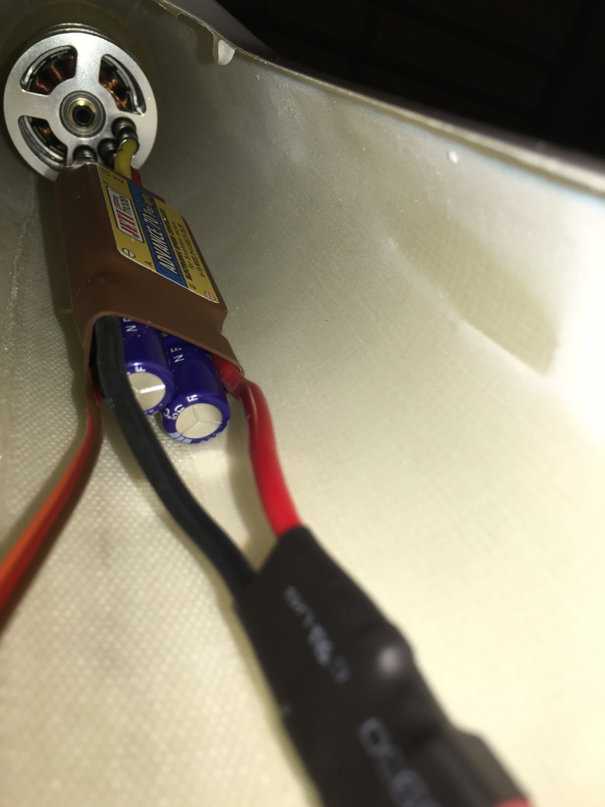
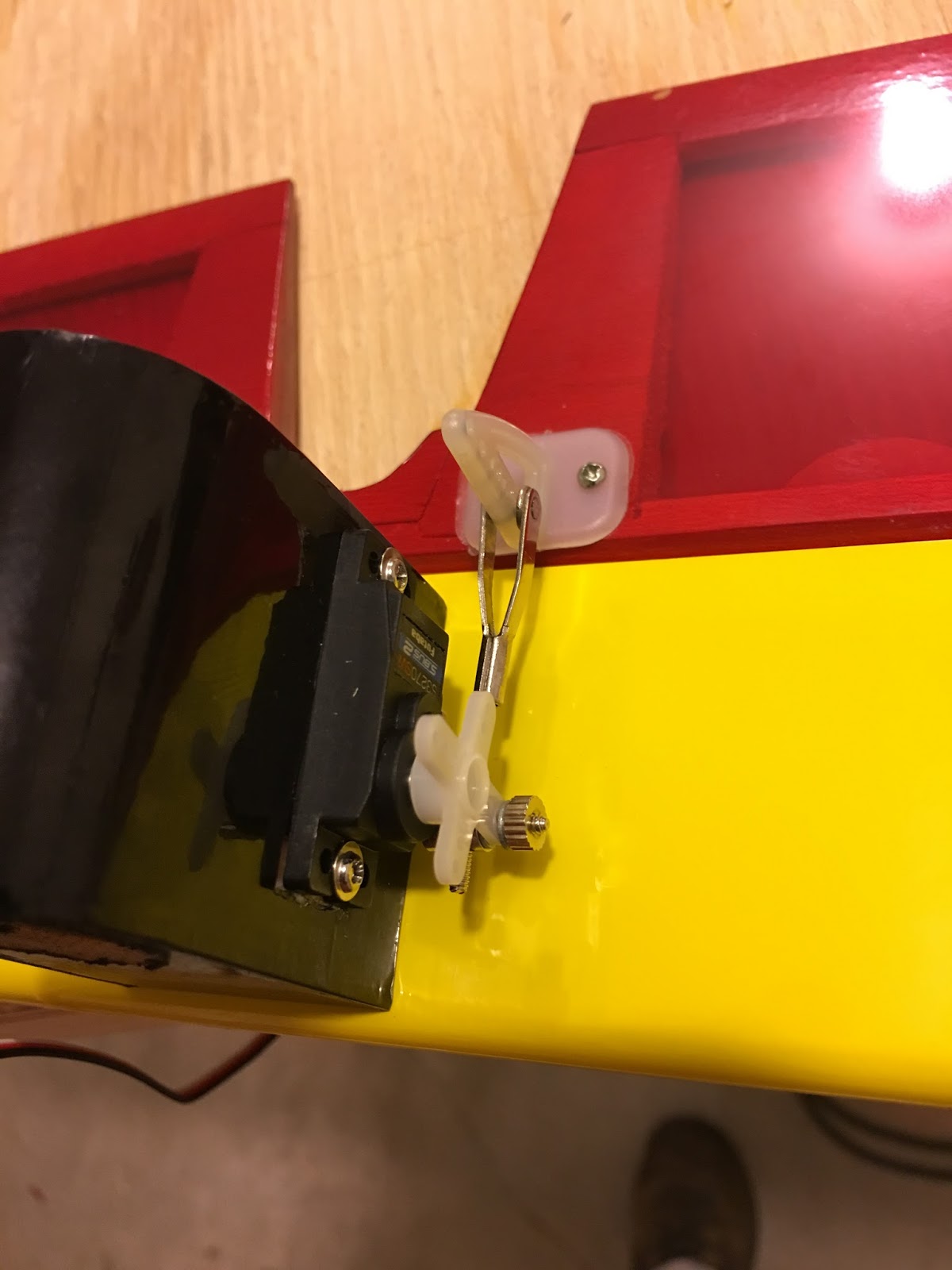
I used velcro to secure the ESC and batteries. This allows me to move the battery back if I want to use a bigger battery.
Be careful checking the CG. This plane can weigh as much as 2500 g (5 pounds).
You have hold the plane up by resting the whole weight of the aircraft on two points under the wings. The sheeting there is very thing you can easily poke a whole through it if your CG testing hardware has small points.
I just used my index fingers (trimmed nails). No way I can use two pencils as we used to with our small free flight models.
Plan on having to adjust the CG as you gain experience on this plane. In my opinion the CG is way to forward. It makes the plane easier to handle but you can definitely see the plane settling in a fast descending glide as soon as the power is off. Moving the CG back makes the plane more difficult to handle but it will glide better. How much back you should move it depends on your flying skills and willingness to sacrifice stability for performance.
First Flight Test
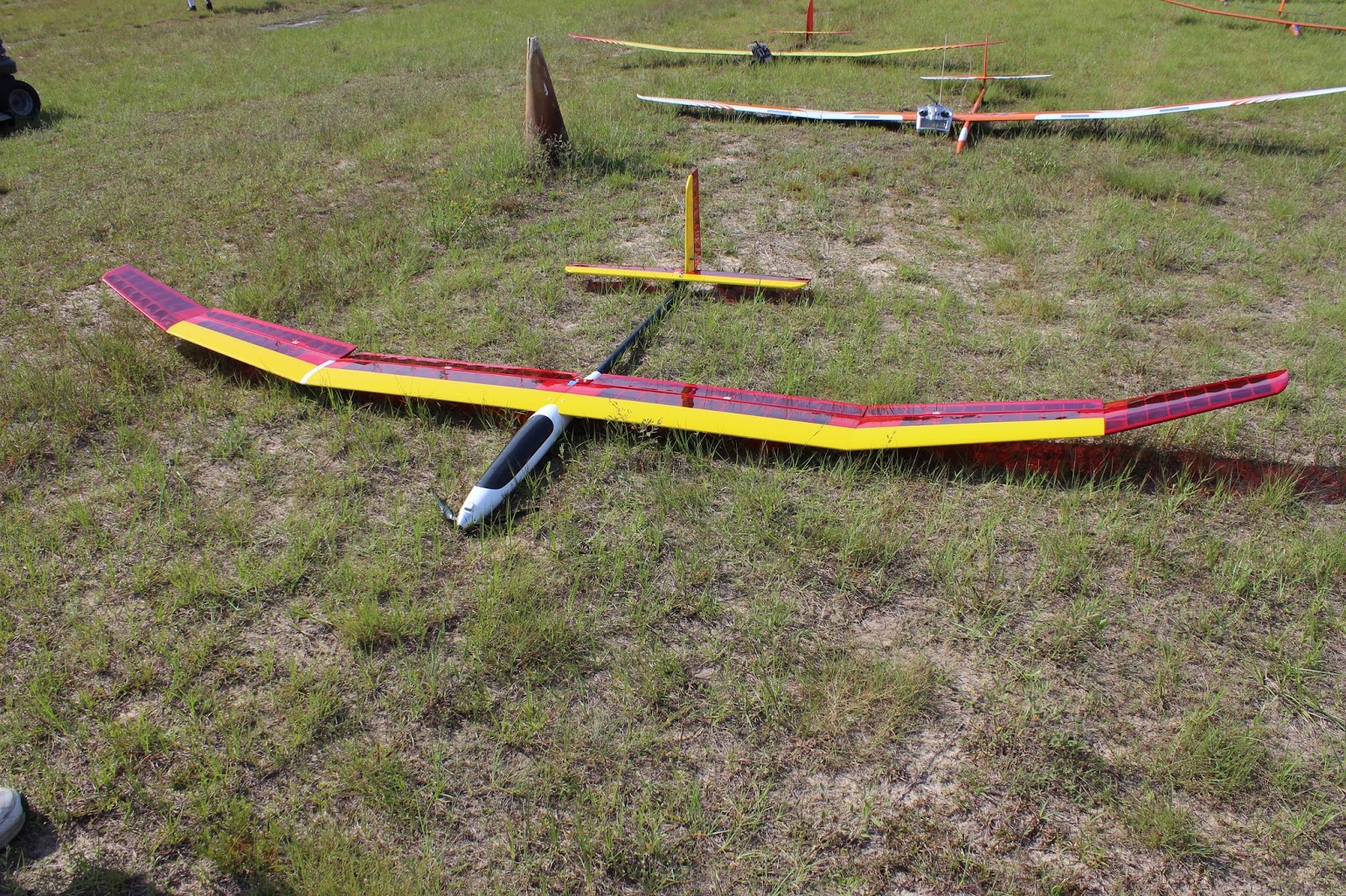
Let me start by saying that after the maiden flight I was pleased.The day of the first flight was not ideal. Winds were 8 MPH gusting to 12 MPH and Temperature was upper 70s. Our field in Florida is close to sea level.
Adding to the stress I test flew this model on the same day we were having our monthly competition. The good side of this is that plenty of experience glider pilots got to see the plane and give out their opinions about it.
Flight tests started with a simple hand launch. Followed by powered climb and glide tests. I will not use the motor in this plane except for competition-like climbs.
Unpowered Glide Test
Flight tests started with a simple hand launch glide.- Verified the CG was 115mm from the leading edge of the wing.
- Verified that all the surfaces were in the neutral position.
- Headed into the wind
- Started to run holding the plane level. Gently moved my arm forward but didn't toss the aircraft, I simply opened my hand and let it go.
- The model settled into a gentle glide straight ahead. No major inputs were needed to keep the glide path.
This first test clearly indicated me that the CG was within acceptable limits and that the incidence angle between the horizontal stab and the wing were also within reasonable limits.
When I was holding the aircraft for launch I noticed how thin the fuselage walls really feel. You can easily feel the walls giving in a little as you hold the aircraft. While I've never heard of anybody squeezing the plane too much and breaking the fuselage, I wish there was a bulkhead in the area where you hold the plane for launch.
Another thing to be alert is that the surface of the fuselage can be very slippery. Sweaty hands and gusting winds can end up in a mishap. Be careful.
No other surprises here.
Powered Climb Tests
First Flight
- Plugged the motor battery.
- Did a very fast (3-seconds) motor test.
- Facing into the wind, flipped the switch that puts my radio in "Launch condition". The flaps go a few degrees down, the motor comes to life to full power. Rudder stays at zero at this point. But I expect to set it a few degrees to compensate for any turning tendencies.
- The propeller literally ripped the plane from my hand. This was a surprise I had hoped to be able to hold the plane but I couldn't. The trust of the power drive and the slippery fuselage made it imposible to hold on to the plane. Plan for that!
- Without inputs, the plane settled in a steep climb without any mayor tendency to turn. I guess I won't have to make the turn compensate during "launch condition".
- I controlled the climb with gentle down input. Mainly because I didn't want to let the nose raise to much in fear of any unusual behavior with the an extreme nose up attitude. (Plus just because the nose is pointing way up doesn't mean our vertical speed will be big).
- After a 20-second climb, I changed the radio to "cruise condition. The motor turns off and all surfaces go to zero. The expectation is that the plane should settle in this best best glide attitude.
- Unfortunately the plane immediately showed a tendency to lower the nose too much and gain speed. I controlled the glide but kept on compensating for a nose down attitude.
- Noticed that the plane slowed down significantly when flying against the wind (10 MPH). Penetration is not this plane forte. Keep in mind that I didn't attempt to use reflex at all on this flight.
- I didn't exercise the flaps at all.
- As gently as I could flew the plane around our flying area and setup for a landing against the wind.
- Landing was predictable and uneventful. No flaps were used for landing.
I noticed that aileron performance was way slower than on my Xplorer. That big wing requires us to use rudder as well. I am used to more aileron authority. I have a lot of work to do on the differential aileron setup on my radio.
I concluded that the nose down attitude was due to too much nose weight. I proceded to remove 7g of weight from the nose. and prepared for a second flight.
I concluded that the nose down attitude was due to too much nose weight. I proceded to remove 7g of weight from the nose. and prepared for a second flight.
Second Flight
- Climb was exactly as before. The prop ripped the plane of my hands. The pitch up attitude during the motor run was still there. Will have to figure out a good attitude for climb and preset that on the "launch condition".
- Upon motor shutdown, the plane settled in a glide.
- The nose down tendency was still there but not as much as the first time.
- I found the plane easy to handle in the air even with the CG moved back. But turns require both aileron and rudder inputs. Considering my radio is programmed to already give some rudder with aileron inputs I found this surprising. The wings move slowly in reaction to the aileron input.
- Rudder authority was not enough in my opinion. I will increase the rudder travel.
- Again I landed the plane upwind without using any flaps. Landing was again predictable although the slow aileron responses made me fearful of a sudden gust of wind putting the plane in an unusual attitude close to the ground.
I didn't want to remove any more weight from the nose at this point. But I believe I could handle another 7grams less on the nose.
After two 20 second climbs with my first motor battery I changed the motor battery.
After two 20 second climbs with my first motor battery I changed the motor battery.
Third Flight:
- Take off was as before. The plane surges forward tracking straight.
- This time I ran the motor for 30 seconds easily getting to the same altitude the winch glider pilots release at. Once the CAM device is installed, the motor will automatically turn off at 150 meters.
- I did a number of glide passes to test stability. The plane flies well without any major trim changes.
- Again I chose not to exercise the flaps.
- The wind had diminished below 10 MPH and since I was already close to the ground decided to land downwind over our large grassy field.
- Landing was attempted downwind.
- This proved to be a mistake as the plane got in the ground effect and glided the whole length of the field a few inches from the ground.
- The plane settled down near the end of the field sliding sideways and ending up with the nose pointing at me. No damage just too much ground speed on touchdown.
On none of the flights I noticed any flutter on any of the surfaces.
The wind whistling on low passes was nice. Not as intense as in the Xplorer but definitely there!
More Observations
The 1300 mAh battery is taxed heavily by this plane ... it demands over 50Amps on the ground! My 1300 mAh motor battery is enough for 2 ALES launches and no more!. (run motor for 30 seconds or until 150 meters is reached)
Note on battery: 2-launches with a 1300 mAh battery may be even a stretch. On my last flight, using a fresh battery I climbed once and upon landing the charger indicated I was already at "storage level capacity" 3.8 V per cell. The batteries are brand new so they may not giving full performance yet.
Word of caution: While testing the power drive on the ground I killed a 25C-rated battery. This was totally my fault. eCalc indicated the motor was going to pull over 40C and the 25C battery could not handle that. My new batteries are rated at 70C continuous. This plane will test the battery limits. Some of those "cheap" batteries may not handle the stated C-rating. I was very nervous about the power drive so I made sure the RX and servos had an alternate power source.
The battery setup described here is more than adequate in a competition environment. (Where you switch motor batteries every flight). Naturally if you are flying for other reasons you may want to get a significantly bigger battery. Also running the motor at full trust may not be indicated in other situations.
Word of caution: My prop-combination makes the motor, ESC and battery very hot. I do not have a temperature sensor mounted on this aircraft so I cannot tell you how much. But let me say this. You CANNOT touch the motor after my on-ground motor test.
This is ok for me because the motor will run for only 20-30 secs and then it will stay off until landing. (ALES competition rules).
The turbo-spinner allows air into the motor. The build-in fan of the Glider Drive will help cool the motor. I expect the hot air to travel through the fuselage and exit on the back. The boom tuve is open on the back.
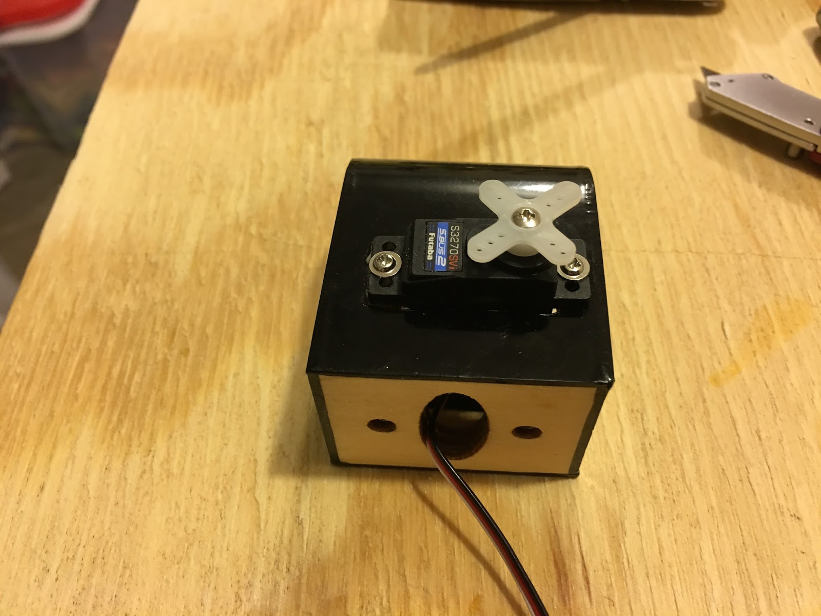
I used a separate 2C-900mAh LIPO to run the RX and the servos. My servos are high-voltage so I do not have to worry about regulators etc.
It should be possible to run the airplane from the ESC power source but I prefer the power redundancy. As a bonus the extra battery helps keep the CG where it needs to be.
The recommended CG is too forward in my opinion. I expect to move further back than it is now.
No terrible habits in the air. But I felt that I didn't have enough aileron authority at low speeds. This is most likely being caused by my aileron-flap mix not being optimized yet.
I felt I didn't have enough rudder authority either.
I need to play more with the control throws until I get more familiar with the airplane.
In the air not bad habits but this is not a beginner airplane either. All turns need to be coordinated to help move those big wings around.
I have a set of mixes that are supposed to help handle the plane:
- flaps move with the ailerons.
- rudder moves with the ailerons.
- flaps move with the elevator.
I am not happy with the current mix settings. I will have to experiment to get a workable "cruise condition".
Adding flaps for thermal flight will change the needed compensations. No idea how much flaps will be needed to stay on a thermal.
Using reflex flaps for speed will also change the needed compensations. My reflex flap travel is limited.
I did not attempt to lower the flaps to 90 degrees yet.
- I do not know yet the speed at which this will safe.
- I do not know what degree of elevator compensation will be needed.
I'll try those settings at altitude next flight session


Back to Part 5
Back to Part 4
Back to Part 3
Back to Part 2
Back to Part 1


