Friday, August 19, 2016

Killing a Perfectly good Power Supply

Killing a Perfectly good Power Supply


For a few years i've had the TP1527PS power supply matched to a TP820CD dual charger and never experienced any problems.

Recently I wanted to share the power supply with another device and lowered the output voltage from 27V to 15V. I then proceeded to to charge 2 4S 5000 mAh batteries. 

Unfortunately the power supply died emitting a loud POP and died with a burn smell.

What in the world happened? I had charged those LIPOs before using a 12V car battery before. Why switching the power supply to 15V would cause it to die.

Well lets think about power requirements.

To charge a 4S 5000 mAh battery we need just over 100 Watts:
4.2V * 4 * 5A * 120% = 100.8 W

To charge 2 4S 5000 mAh battery we need just over 200 Watts:
2 * 4.2V * 4 * 5A * 120% = 201.6 W

The TP1527PS states that it can provide 350W at 15V there. The assumption was that since our power requirements are about 60% of the maximum supported by the Power Supply we would be ok.

As it turn out this was wrong. The Power Supply gave up and died while charging the second set of batteries.

Why? Any ideas?

All I can think is that the 201.6W pulled continuously of the power supply caused something to fail. That is sad considering this is rated for 350W at 15V... 

sad for a power supply costing $150.00 + 


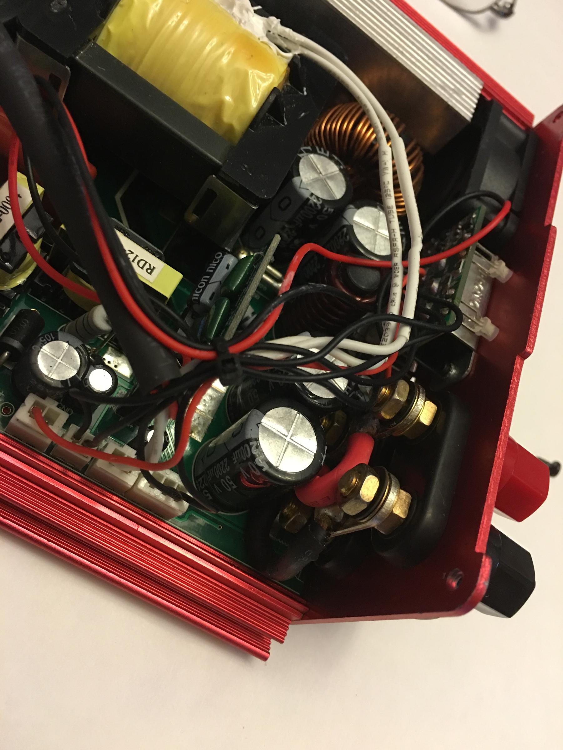
There are really not two channels. But two sets of connectors connected to the same output channel:


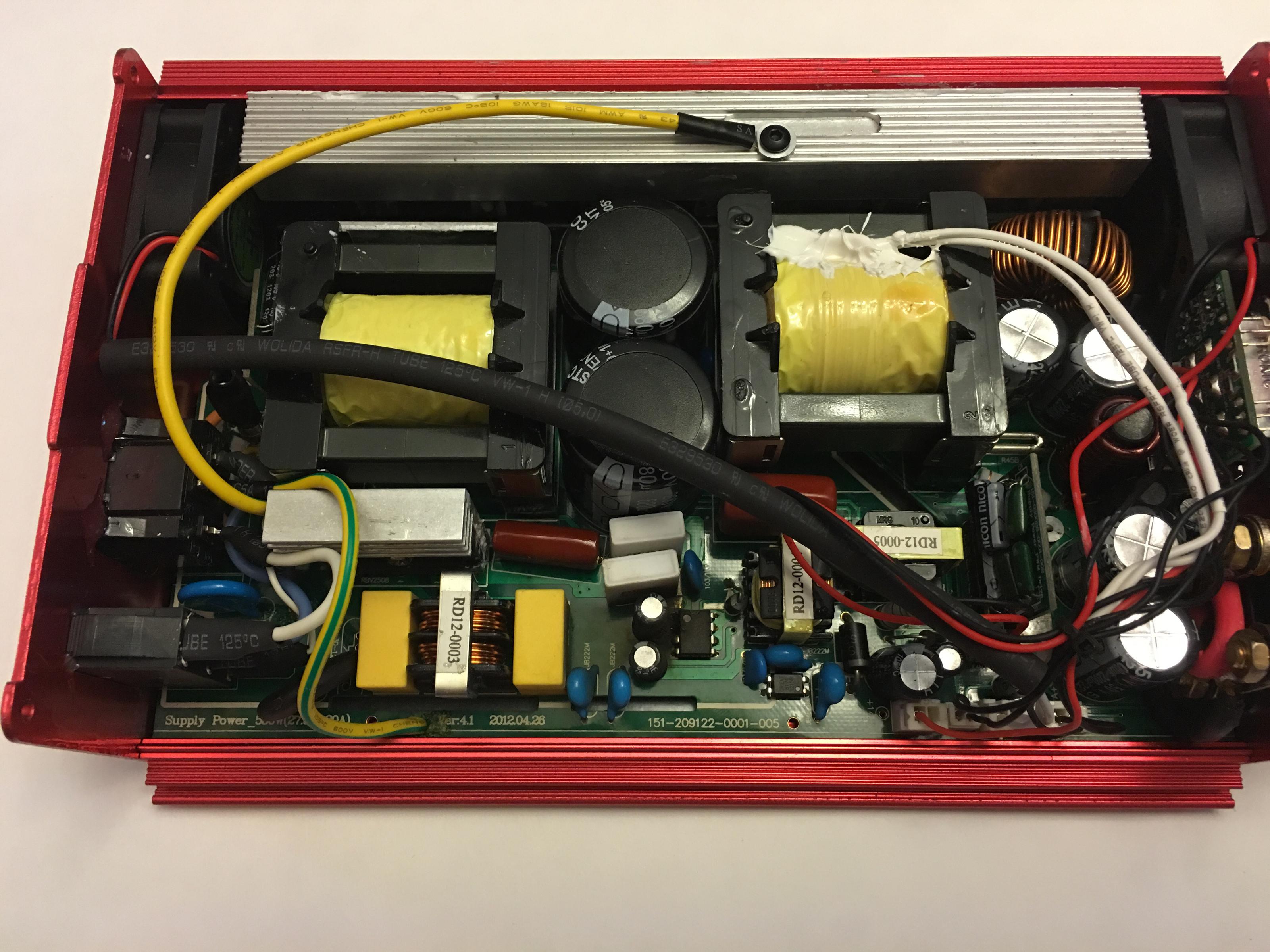
Hard to see if there is something else broken here:

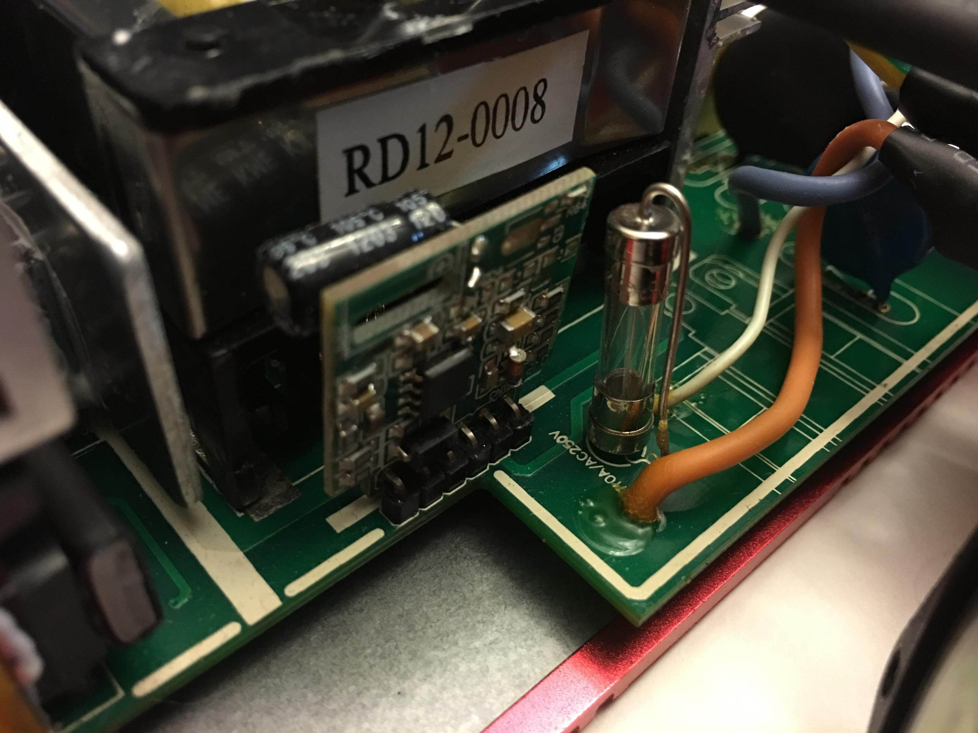
The only fuse in the box seems to be in good shape:


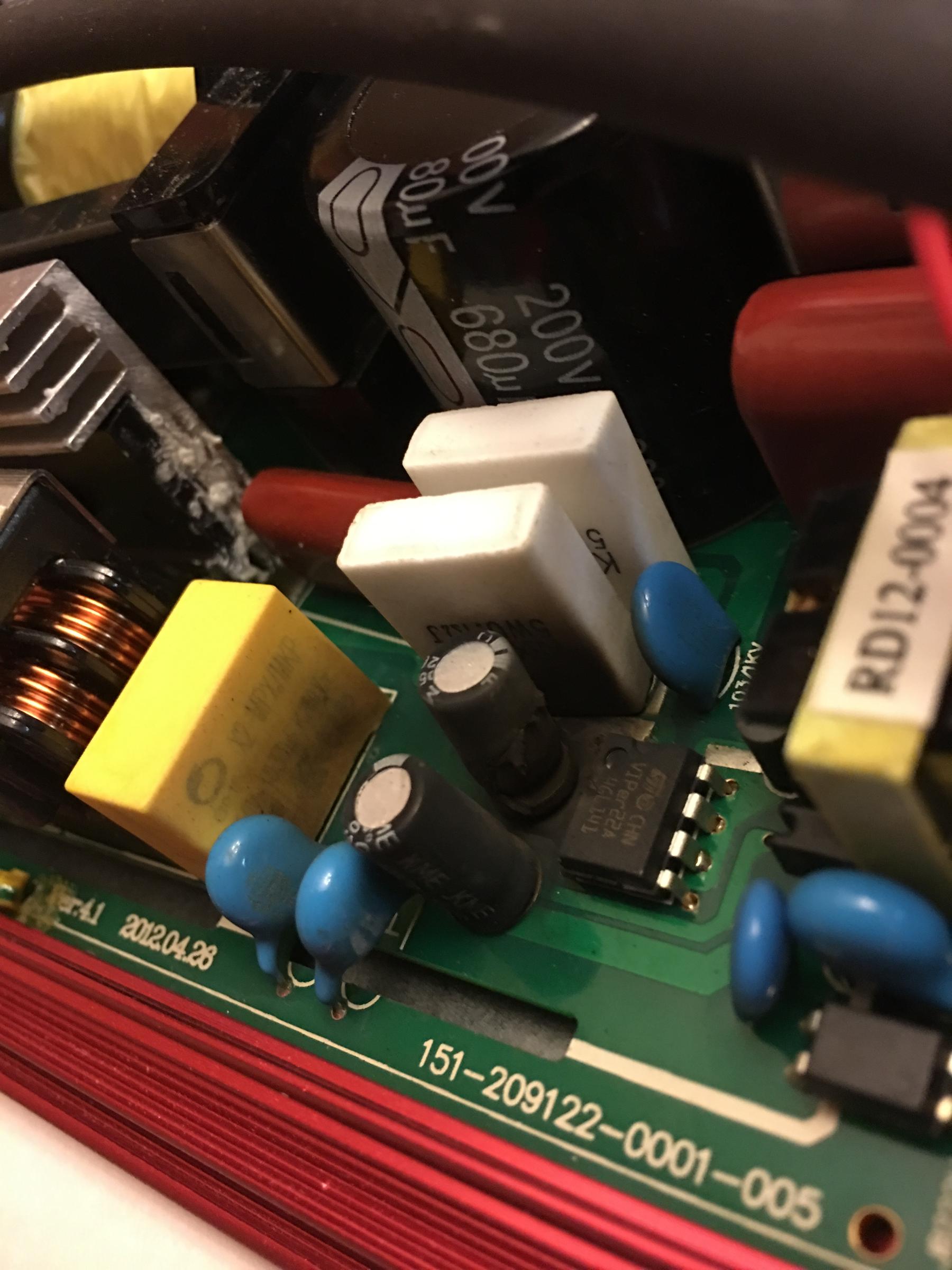
The capacitor looks fried ... It may have taken out the IC next to it too... 
I may get bold and attempt to replace the capacitor


Capacitors just fail sometimes


Wednesday, August 10, 2016

Charsoon Antimatter Charger

Charsoon Antimatter Charger 250W 10A


Quick Links:


I was recently asked if I wanted to review this new charger. I am always looking for inexpensive quality products to recommend to beginners so I naturally agreed to give it a try.

A couple of two weeks latera brand-new review unit arrived directly from China. 

The unit came undamaged in a padded envelope. The charger box was packed carefully and protected the contents without any filler material. 

Opening the box we found the following:
  • 22 page English manual,
  • Male Dean-type connector charger cable.
  • Combination J-Connector Futaba and BEC JST Female charger cable.
  • XT-60 Connector charger cable.
  • Alligator battery plugs with female banana connectors (to connect charger to a 12V battery)
  • Charger unit 
Note: No DC Power supply is included.

I liked the well written English manual. 
The charger unit features:

  • Built-in standard balance port board (no Thunderpower balance ports). It accommodates 2S to 5S batteries.
  • Built-in fan.
  • 4 multi-function buttons
  • LCD screen
  • Built-in  input cables with male-banana input power (Input is 12V-18V).
  • DC input jack (up to 18V 6A). This jack features self-resetting circuit breaker.
  • A USB Port to connect to a computer. For configuration and to save and restore settings from a PC. Possibly firmware upgrades can be done via this port.
My first impression is that the unit is well put together and is similar in form-factor to other units we've seen in the field. However there is a long list of features listed in the manual mainly promising easy of use and security

The balance board is built-into the unit. this makes it more compact.

For input voltage the included leads can be used or the jack. Note that the Jack is limited to 6A.
A two line LCD and four multi-function buttons are provided.
Ready to use alligator clips are provided.
The unit comes with ready-to-use alligator clips that can be attached to the input leads. These can be used to connect directly to a 12V battery.

Be aware that using these banana connectors produces a spark on the battery leads. Care must be taken to minimize this.

It is not clear if the internal electronics protect the charger from the sudden voltage surge.

The standard banana plugs can be used with a suitable power supply. Be mindful that input voltages cannot exceed 18V. This unit is not meant to be used with 24V power supplies.

Note: Do not use this charger with ThunderPower batteries with the ThunderPower balance connectors. This charger is intended to be used only with standard JST balance connectors.

Charge Test

I decided to use a small 12V battery instead of a power supply. When connecting to the battery there was a noticeable spark when connecting the alligator clips. The unit came up immediately.  It is my expectation that the internal circuits will protect the charger from the voltage surge. 

I found the menu system easy to navigate if you have the navigation flowchart next to you. Unless you are very familiar with this kind of charger clicking around may not be best way to find a specific function. For instance without the manual it would have been very hard to  to find the "Preset Testing" mode (You have to press the STOP/BATT TYPE button for 3-seconds).

Note: Do not lose the manual.

Input Voltage 12.34 V
Battery Voltage 11.64 V
Internal Temperature 30ยบ C
I used a 3S 2100 mAh LIPO battery as a test battery. This is battery must be charged at 1C. The balance connectors are standard JST and were plugged directly into the board on the side of the charger. The XT60 connector was plugged to the supplied charge lead. The charger itself was plugged a 12V battery for input power.

As a control device I used my trusty ThunderPower 820CD (a charger retailing for almost 3-times as much as the Antimatter Charger) connected to a high performance 24V power supply.


On the Antimatter Charger, I used the "Present Testing" mode to test the battery internal resistance and voltages. The batteries internal resistance was:

I did the same test using the ThunderPower charger. I found a small discrepancy on the internal resistance:

I proceeded to change the mode of the Charger to "LIPO battery balance charging" and rapidly programmed it charge a battery with 2100mAh capacity. I didn't have to specify the number of cells because it automatically detected it from the balance port used.

Anybody who has used any balancing charger should have no issues using this charger. A complete beginner is advised to read about charging LIPO batteries to understand the nomenclature and the procedures.

Warning: Typing the wrong mAh value could damage the battery.

The manual indicates there several sensors in the charger protect the device and the battery. There is a temperature sensor and other sensors stop charging if there is over voltage or excessive time has elapsed. All these parameters can be changed. I left all these values on the default.

33 minutes later a set of continues beeps announced that the battery was charged.


After the charge is complete we can check the voltages by putting the charger in "Present Testing" mode. During the charge is possible to switch between status and cell the voltages by pressing the [Dec] and [Inc] buttons.


I proceeded to verify the reported voltages on my ThunderPower charger:


Storage Test

I disconnected the Antimatter charger and was happy to confirm that the battery settings I had programmed were still there. There is no need to save the settings unless you plan to charge several kinds of batteries. 

I setup the charge to discharge the battery to "storage" level.


The fan immediately came on as the battery is discharged


It took 36 minutes to discharge the battery to "storage level".

Again we compared the voltages


Special Battery Operations

Charging and Preparing for Storage are the most common tasks users do with chargers. 
This charger however offers a few more programs:
  1. Charge in Unbalance Mode. (called in the manual Normal Charge Mode). This is definitely not recommended. 
  2. Fast Charging. You can specify the maximum amps for fast charging. Care must be taken not to exceed the C-capacity of the battery when doing this. I personally never charge batteries at a rate higher than 1-C.
  3. Pre-Charging. This is a last-ditch effort mode to try to "resurrect" an otherwise dead battery. Some over-discharged batteries can be "revived" if pre-charged to a certain level before a normal balance charge. I would use this mode only as a last-ditch effort to salvage a battery. If the battery revives I would always keep it clearly marked and pay extra attention to it. I would check the internal resistance of the battery very often if a battery has been over discharged.
  4. Discharging. You can set a target voltage and discharge the battery to that level. I Personally have never used this mode on any charger unless I'm trying to test if a battery is healthy.
  5. Cycle battery. In this mode it is possible to discharge and charge a battery. This can be useful if you are testing a suspicious battery and want to make sure the battery behaves in a healthy manner.
  6. Monitor. You can monitor each batteries cells while the battery is being used. Note that this mode is not counting how many milliamps are being taken out of the battery. It just indicates under-voltage or over-voltage situations.

 Special Operations

  1. Brushed motor mode. Brushed DC motors can be directly controlled by the charger.  This can be useful in testing situations. Note that brushless DC motors cannot be controlled at all by this charger. I wouldn't plug an ESC directly to the charger either.
  2. Foam Cut. The charger can be used to provide power to a FOAM cutter.

I liked

  • Price is very affordable, especially for a beginner.
  • English manual written in good English.
  • Built in balance board. Keeps things compact.
  • Automatic selection of LIPO cell count depending on which balance port is being used.
  • Fine-tuning of many parameters. For example you can control the minimum voltage to discharge a LIPO battery. As well many other parameters.
  • Ready to use charge cables provided for different kinds of connectors. 

    I didn't like

    • The volume for the key beeper is too loud for indoor use. One of the first things I did was to mute the key beeper. 
    • Connecting the charger to a 12V battery using the alligator clips will produce a spark. Hopefully the electronics inside the charger will protect the charger from the sudden voltage surge.
    • Input voltage is limited to a maximum of 18V which means I cannot use a 24V heavy duty power supply I normally use on my other charger.
    • Selecting one of the 10 memory is a bit cumbersome and error prone. You must change the charger mode to "PROGRAM SELECT/Save Settings" or "PROGRAM SELECT/Load Settings" and then select the memory location you intend to save-to or load-from. A small card will have to kept as a reminder of what is saved on each memory location. Other chargers show battery settings associated with each memory location so you don't have to remember that save location 07 contains the settings to charge a 3S 2100mAh LIPO.
    • Saving saves a "battery set" which to me means that it will save the settings for charging a LIPO battery a PB battery a NiCD battery... all in one memory location. This is different from other chargers where a saved location is associated with one specific battery. 

    Links and other Information

    Monday, May 16, 2016

    HobbyKing Aether 3.7 Review Part 6

    Weight and Balance


    The manual indicates that the CG should be at 115mm from the leading edge of the wing.
    Like on the previous version of the Aether, even moving both the RX and Motor battery all the way forward I still had to add weight to the nose (21 g)

    I secured the ballast externally using electrical tape so that I can move it easily. Once the CG is in the sweet spot I can mark the CG spot and re-balance the model internally.

    I used velcro to secure the ESC and batteries. This allows me to move the battery back if I want to use a bigger battery.

    Be careful checking the CG. This plane can weigh as much as 2500 g (5 pounds).
    You have hold the plane up by resting the whole weight of the aircraft on two points under the wings. The sheeting there is very thing you can easily poke a whole through it if your CG testing hardware has small points.
    I just used my index fingers (trimmed nails). No way I can use two pencils as we used to with our small free flight models.

    Plan on having to adjust the CG as you gain experience on this plane. In my opinion the CG is way to forward. It makes the plane easier to handle but you can definitely see the plane settling in a fast descending glide as soon as the power is off. Moving the CG back makes the plane more difficult to handle but it will glide better. How much back you should move it depends on your flying skills and willingness to sacrifice stability for performance.

    First Flight Test

    Let me start by saying that after the maiden flight I was pleased.

    The day of the first flight was not ideal. Winds were 8 MPH gusting to 12 MPH and Temperature was upper 70s. Our field in Florida is close to sea level.

    Adding to the stress I test flew this model on the same day we were having our monthly competition. The good side of this is that plenty of experience glider pilots got to see the plane and give out their opinions about it.

    Flight tests started with a simple hand launch. Followed by powered climb and glide tests. I will not use the motor in this plane except for competition-like climbs.

    Unpowered Glide Test

    Flight tests started with a simple hand launch glide.
    1. Verified the CG was 115mm from the leading edge of the wing.
    2. Verified that all the surfaces were in the neutral position. 
    3. Headed into the wind
    4. Started to run holding the plane level. Gently moved my arm forward but didn't toss the aircraft, I simply opened my hand and let it go.
    5. The model settled into a gentle glide straight ahead. No major inputs were needed to keep the glide path.  
    This first test clearly indicated me that the CG was within acceptable limits and that the incidence angle between the horizontal stab and the wing were also within reasonable limits.

    When I was holding the aircraft for launch I noticed how thin the fuselage walls really feel. You can easily feel the walls giving in a little as you hold the aircraft. While I've never heard of anybody squeezing the plane too much and breaking the fuselage, I wish there was a bulkhead in the area where you hold the plane for launch.

    Another thing to be alert is that the surface of the fuselage can be very slippery. Sweaty hands and gusting winds can end up in a mishap. Be careful. 

    No other surprises here.

    Powered Climb Tests 

    First Flight
    1. Plugged the motor battery.
    2. Did a very fast  (3-seconds) motor test.
    3. Facing into the wind, flipped the switch that puts my radio in "Launch condition". The flaps go a few degrees down, the motor comes to life to full power. Rudder stays at zero at this point. But I expect to set it a few degrees to compensate for any turning tendencies.
    4. The propeller literally ripped the plane from my hand. This was a surprise I had hoped to be able to hold the plane but I couldn't. The trust of the power drive and the slippery  fuselage made it imposible to hold on to the plane. Plan for that!
    5. Without inputs, the plane settled in a steep climb without any mayor tendency to turn. I guess I won't have to make the turn compensate during "launch condition".
    6. I controlled the climb with gentle down input. Mainly because I didn't want to let the nose raise to much in fear of any unusual behavior with the an extreme nose up attitude. (Plus just because the nose is pointing way up doesn't mean our vertical speed will be big).
    7. After a 20-second climb, I changed the radio to "cruise condition. The motor turns off and all surfaces go to zero. The expectation is that the plane should settle in this best best glide attitude. 
    8. Unfortunately the plane immediately showed a tendency to lower the nose too much and gain speed. I controlled the glide but kept on compensating for a nose down attitude.  
    9. Noticed that the plane slowed down significantly when flying against the wind (10 MPH). Penetration is not this plane forte. Keep in mind that I didn't attempt to use reflex at all on this flight.
    10. I didn't exercise the flaps at all. 
    11. As gently as I could flew the plane around our flying area and setup for a landing against the wind.
    12. Landing was predictable and uneventful. No flaps were used for landing.
    I noticed that aileron performance was way slower than on my Xplorer. That big wing requires us to use rudder as well. I am used to more aileron authority. I have a lot of work to do on the differential aileron setup on my radio.
    I concluded that the nose down attitude was due to too much nose weight. I proceded to remove 7g of weight from the nose. and prepared for a second flight.

    Second Flight
    1. Climb was exactly as before. The prop ripped the plane of my hands. The pitch up attitude during the motor run was still there. Will have to figure out a good attitude for climb and preset that on the "launch condition".
    2. Upon motor shutdown, the plane settled in a glide. 
    3. The nose down tendency was still there but not as much as the first time.
    4. I found the plane easy to handle in the air even with the CG moved back. But turns require both aileron and rudder inputs. Considering my radio is programmed to already give some rudder with aileron inputs I found this surprising. The wings move slowly in reaction to the aileron input.
    5. Rudder authority was not enough in my opinion. I will increase the rudder travel.
    6. Again I landed the plane upwind without using any flaps. Landing was again predictable although the slow aileron responses made me fearful of a sudden gust of wind putting the plane  in an unusual attitude close to the ground.
    I didn't want to remove any more weight from the nose at this point. But I believe I could handle another 7grams less on the nose.

    After two 20 second climbs with my first motor battery I changed the motor battery.

    Third Flight:
    1. Take off was as before. The plane surges forward tracking straight.
    2. This time I ran the motor for 30 seconds easily getting to the same altitude the winch glider pilots release at. Once the CAM device is installed, the motor will automatically turn off at 150 meters.
    3. I did a number of glide passes to test stability. The plane flies well without any major trim changes. 
    4. Again I chose not to exercise the flaps.
    5. The wind had diminished below 10 MPH and since I was already close to the ground decided to land downwind over our large grassy field.
    6. Landing was attempted downwind.
    7. This proved to be a mistake as the plane got in the ground effect and glided the whole length of the field a few inches from the ground.
    8. The plane settled down near the end of the field sliding sideways and ending up with the nose pointing at me. No damage just too much ground speed on touchdown.
    On none of the flights I noticed any flutter on any of the surfaces.

    The wind whistling on low passes was nice. Not as intense as in the Xplorer but definitely there!

    More Observations

    The 1300 mAh battery is taxed heavily by this plane ... it demands over 50Amps on the ground! My 1300 mAh motor battery is enough for 2 ALES launches and no more!. (run motor for 30 seconds or until 150 meters is reached)

    Note on battery: 2-launches with a 1300 mAh battery may be even a stretch. On my last flight, using a fresh battery I climbed once and upon landing the charger indicated I was already at "storage level capacity" 3.8 V per cell. The batteries are brand new so they may not giving full performance yet.

    Word of caution: While testing the power drive on the ground I killed a 25C-rated battery. This was totally my fault. eCalc indicated the motor was going to pull over 40C and the 25C battery could not handle that. My new batteries are rated at 70C continuous. This plane will test the battery limits. Some of those "cheap" batteries may not handle the stated C-rating. I was very nervous about the power drive so I made sure the RX and servos had an alternate power source.

    The battery setup described here is more than adequate in a competition environment. (Where you switch motor batteries every flight). Naturally if you are flying for other reasons you may want to get a significantly bigger battery. Also running the motor at full trust may not be indicated in other situations.

    Word of caution: My prop-combination makes the motor, ESC and battery very hot. I do not have a temperature sensor mounted on this aircraft so I cannot tell you how much. But let me say this. You CANNOT touch the motor after my on-ground motor test.

    This is ok for me because the motor will run for only 20-30 secs and then it will stay off until landing. (ALES competition rules).

    The turbo-spinner allows air into the motor. The build-in fan of the Glider Drive will help cool the motor. I expect the hot air to travel through the fuselage and exit on the back. The boom tuve is open on the back.

    I used a separate 2C-900mAh LIPO to run the RX and the servos. My servos are high-voltage so I do not have to worry about regulators etc.

    It should be possible to run the airplane from the ESC power source but I prefer the power redundancy. As a bonus the extra battery helps keep the CG where it needs to be.

    The recommended CG is too forward in my opinion. I expect to move further back than it is now.

    No terrible habits in the air. But I felt that I didn't have enough aileron authority at low speeds. This is most likely being caused by my aileron-flap mix not being optimized yet.

    I felt I didn't have enough rudder authority either.

    I need to play more with the control throws until I get more familiar with the airplane.

    In the air not bad habits but this is not a beginner airplane either. All turns need to be coordinated to help move those big wings around.

    I have a set of mixes that are supposed to help handle the plane:
    1. flaps move with the ailerons.
    2. rudder moves with the ailerons.
    3. flaps move with the elevator.
    I am not happy with the current mix settings. I will have to experiment to get a workable "cruise condition". 

    Adding flaps for thermal flight will change the needed compensations. No idea how much flaps will be needed to stay on a thermal.

    Using reflex flaps for speed will also change the needed compensations. My reflex flap travel is limited.

    I did not attempt to lower the flaps to 90 degrees yet.
    1. I do not know yet the speed at which this will safe.
    2. I do not know what degree of elevator compensation will be needed.
    I'll try those settings at altitude next flight session


    Back to Part 5
    Back to Part 4
    Back to Part 3
    Back to Part 2
    Back to Part 1

    HobbyKing Aether 3.7 Review Part 5

    Power System

    Power system information in the manual is very lean.


    The expectation is that the modeler will pick the power drive of choice. Considering that plane is being marketed as an entry level ALES plane it would have been beneficial if they would have specified the power drive fully. (motor+esc+prop+battery).
    I decided to use HobbyKing's motor recommendation: 

    This is a relatively inexpensive "outrunner in a can" glider motor. It retails for about  $36.00.

    My initial calculations on eCalc called for a 14x9 prop. However this proved to be problematic

    Warning: eCalc does not explicitly tell how what size folding propeller "yoke" is using in its calculations. This lead me to believe I could use a 14x9 prop safely. This proved to be wrong. the 55mm turbo-spinner combination proved to be too much for my battery in real life.

    After talking with the eCalc folks it was pointed out that they used 42mm for their calculations. I am using a 55mm turbo-spinner-yoke combination. Therefore I recomputed by power requirements by adding 13mm to prop size. 

    This is the second set of calculations in eCalc using a 14x8 propeller and a 55mm folding prop yoke:

    Follow this link for the actual eCalc worksheet .

    Warning: This prop-motor combination will damage you battery if it cannot handle 40-50C continous discharge. 

    Warning: This glider does not cool the motor properly for continuous operation beyond 30 secs at full throttle level.

    On the maiden flight the motor at full throttle ripped the plane of my hands. Climbing to altitude per ALES rules should not be a problem.


    This are the initial power components. The battery with the white tape was replaced because it could not handle the current load.

    The ESC is rated to 70 Amps.

    The small battery is my receiver and servo battery.


    This battery has no problem handling the 50 Amp load that the prop and motor demand.


    It is necessary to enlarge the center hole so that the motor fits correctly.

    There are 8 pre-drilled holes on the fiberglass firewall. 4 are used to mount the motor. I enlarged the other 4 so that the motor would have some "air-intakes for ventilation"

    After installing the motor. We can see that there is some space for air to squeeze into the motor. The built-in fan and the motion air coming through the "turbo spinner" should provide enough cooling for the 30-sec motor run.


    There is plenty of space in the Aether to mount the motor.
    The rear shows the Glider Drive built-in fan.
     I used a 55mm turbo spinner. This spinner allows air to penetrate the motor for cooling.


    I tested the whole affair on the ground using an inline power meter. this allowed me to double check eCalc.


    Go to Part 6
    Back to Part 4
    Back to Part 3
    Back to Part 2
    Back to Part 1